
When an OEM's harness shop overseas decided to automate their cable stripping line, they ran into a wall nobody saw coming. Every J1939/15 sample they fed through the demo unit failed—the jacket wouldn't release cleanly, the copper insulation was getting nicked, and the strip quality wasn't repeatable enough to run unattended.
The shop foreman didn't ask the cable supplier for a softer material. He asked a harder question: "Is your J1939/15 actually designed to run on automation?" That question exposed something most engineers never think about: J1939-11 and J1939-15 aren't just different on the spec sheet—they're different machines, with different tolerances and different failure modes.
"Every J1939/15 cable sample they ran through the demo unit failed—the jacket wouldn't release cleanly, and the strip quality wasn't repeatable enough to run unattended. The customer didn't ask us for a softer cable. He asked whether we could build a J1939/15 that his line could actually run."
— CASMO R&D Team, recounting a real field integration challenge
That moment is why we're writing this. Because if you're sourcing CAN bus cable for a heavy-duty platform and someone tells you J1939/11 and J1939/15 are "basically the same, just shielded vs unshielded," you're getting a half-truth that costs real money downstream—in EMC failures, harness rework, fleet warranty claims, and yes, in automation systems that won't run reliably.

The Short Answer
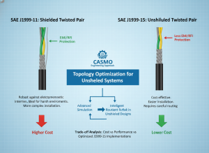
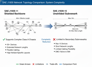
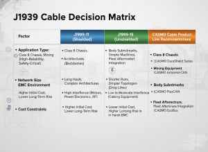
J1939-11 is a shielded twisted pair (STP) standard that supports 30 ECUs with relaxed geometric requirements and high EMC margin; J1939-15 is an unshielded twisted pair (UTP) standard limited to 10 ECUs with mandatory edge-rate control and a critical 10 mV voltage imbalance limit. Choose J1939-11 for primary chassis backbones with severe EMC environments and flexible topology; choose J1939-15 only for secondary subnetworks where total cable length and node count are tightly controlled, and your harness shop can guarantee round cable geometry and automation-friendly construction.
Why This Question Matters
You're evaluating physical layer options for a J1939 network, and the decision seems straightforward: shield or no shield. But here's what makes it non-obvious: both standards run at the same 250 kbit/s data rate, both specify 120 Ω characteristic impedance, both use the same color convention (yellow CAN_H, green CAN_L), and both promise a -40°C to +125°C operating envelope.
The spec sheet says "basically the same." The real world says otherwise.
Over the past 15 years in heavy-duty vehicle engineering, I've reviewed hundreds of field failures tied to J1939 physical layer choices. The pattern is consistent: when engineers spec J1939/15 because it's cheaper, but don't discipline the topology and cable geometry requirements, they hit one of three walls:
- EMC failures in integration — the vehicle passes individual ECU bench testing, but when you plug 8-10 nodes onto a real 40-meter harness, you get radiated noise that wasn't predicted
- Harness automation problems — like the case above, the cable looks compliant on paper but won't process repeatably
- Field warranty surprises — mixed-generation nodes on the same network, or retrofit scenarios where J1939/11 ECUs get connected to J1939/15 backbones, creating ground loop failures
This guide walks through the five technical dimensions that separate a correct J1939/15 design from an expensive mistake.
The Five Key Differences: J1939-11 vs J1939-15
Difference #1: Signal Edge Rate Became Mandatory (Not Just Recommended)
The spec sheet:
- SAE J1939/11: rise/fall times of 200–500 ns are recommended
- J1939/15: rise/fall times of 200–500 ns are required, with 500 ns as the preferred target
Why this matters:
When SAE removed the shield in J1939/15, they removed the cable's primary EMC defense. The only remaining control lever was the transceiver's edge rate. A 500 ns edge radiates far less than a 200 ns edge—but a slower edge also tightens your timing budget on long buses with multiple nodes.
This is a deliberate engineering trade. You gain cost savings (no shield). You lose EMC margin and timing headroom.
The practical consequence:
- J1939/11 caps networks at 30 ECUs with flexible topology
- J1939/15 caps networks at 10 ECUs maximum (per SAE J1939/15 §6.4)
The slower edges and longer permitted stub lengths (3 m vs 1 m in /11) consume timing margin that a 30-node bus simply doesn't have. This is why the same OEM often uses /11 on the chassis backbone and /15 on a body-builder subnetwork—/15 isn't a cheaper /11, it's a different operating point.
Difference #2: The 10 mV Imbalance Limit (J1939/15's Critical Constraint)
The spec sheet:
- J1939/11: no voltage imbalance limit specified
- J1939/15: voltage imbalance between CAN_H and CAN_L cannot exceed 10 mV peak-to-peak (AC-coupled measurement, CAN_H minus inverted CAN_L)
Why this matters:
In an unshielded pair, any asymmetry between the two conductors converts your differential signal into common-mode noise. Common-mode noise becomes radiated EMI. The 10 mV limit is what stops your harness from turning into a 250 kHz antenna.
Where does asymmetry come from? Cable geometry.
Specifically:
- The two conductors must sit in mirror-image dielectric environments
- Insulation thickness must be uniform around each conductor
- The pair must maintain consistent twist geometry along the entire length
- The cable's cross-section must remain round under jacket compression
The harness automation problem:
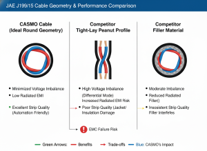
Most low-cost J1939/15 cable in the market uses tight-lay (compact) stranding—pulling the two insulated conductors tightly against each other, then extruding the jacket directly over that profile. The result looks "efficient" but has a peanut-shaped or figure-eight outline, with the jacket locked to the conductor twist.
Two consequences follow:
-
EMC failure mode: The two conductors are no longer in symmetrical dielectric environments. Differential-to-common-mode conversion goes up. The 10 mV limit gets exceeded, and the cable fails radiated emissions testing.
-
Harness shop failure mode: When a stripping blade tries to score a clean ring around the cable, the jacket tears along the helical seam between the two conductors (path of least resistance). The strip tail comes off ragged, the conductor insulation gets nicked, and the automation line stops.
These are the same defect viewed from two angles. EMC engineers see it as differential imbalance. Manufacturing engineers see it as bad strip quality. They are talking about the same cable.
Difference #3: How Bus Length Is Measured (Same Number, Different Meaning)
The spec sheet:
Both J1939-11 and J1939-15 specify a maximum bus length of 40 meters. Read the fine print.
J1939/11: bus length is measured as the backbone between the two terminating resistors, excluding stubs
- With 30 nodes each allowed up to 1 m of stub, your effective wire-in-vehicle can exceed 70 meters
J1939/15: bus length is measured as total backbone including all stubs
- With 10 nodes each allowed up to 3 m of stub, the math becomes a constraint: 10 nodes × 3 m = 30 m of stub, leaving only 10 m of trunk
The practical consequence:
If you're laying out a Class 8 chassis or off-highway machine and you've sized your routing assuming "/15 gives me 40 m to play with," you may already be out of compliance before the first cable is cut. The standard penalizes long-stub topologies in /15 networks, and the only recovery path is disciplined topology—shorter stubs, fewer T-junctions, controllers placed closer to the backbone.
Difference #4: Shield Drain Wire Handling in Mixed Scenarios
The issue:
J1939/15 explicitly addresses what happens when J1939/11-compliant equipment touches a J1939/15 network (see Appendix F):
- A J1939/11 diagnostic tool plugged into a J1939/15 network: CAN_SHLD floats
- A J1939/11 ECU connected to a /15 network via its 3-pin pigtail: CAN_SHLD floats, a sealing plug fills the unused cavity
The drain wire is not optional; it's not "best practice"—it's a compliance requirement. If you tie the drain wire of a J1939/11 cable to ground on a /15 network, you create a ground loop and violate SAE's single-point-grounding rule.
Real-world scenario:
This is common in fleet aftermarket and mining equipment retrofits, where a Tier-2 supplier's /11 ECU gets integrated onto an OEM's /15 backbone. The shield handling is where most field failures originate—almost always a wiring error, not a cable defect.
Difference #5: Cable Construction Requirements (Thermoset Jacket Becomes Non-Negotiable)
The spec sheet:
Both standards require the cable to meet SAE J1128 (low-tension primary cable types). Both reference GXL and SXL as compliant insulation/jacket systems. J1939/15 additionally allows TXL (thin-wall, weight-reduced).
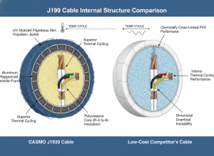
The "XL" in all three is critical: cross-linked thermoset, not thermoplastic. Cross-linking is what gives the cable:
- Its -40°C to +125°C operating range
- Long-term aging resistance (3000 hours at 125°C per ISO 6722)
- Dimensional stability under thermal cycling
The manufacturing trade-off:
Most low-bid J1939 cable uses chemically cross-linked PVC, which technically meets J1128 but is harder to extrude with consistent geometry—especially over a non-tight-laid pair. The jacket either follows the conductor profile (giving you the peanut-shape problem above) or requires a filler material to round out the cross-section (which adds cost and weight, and complicates stripping).
Irradiation-cross-linked polyolefin (XLPE) jackets can be processed without fillers and still hold a round cross-section, but the process equipment is expensive and the manufacturing window is tight. This is why the supplier base for "J1939/15 with round cross-section, no filler, automation-friendly stripping" is small. Most cable mills aren't equipped for it; the ones that are usually serve aerospace or specialty markets where volumes don't fit heavy-duty vehicle pricing.
Quick Reference: J1939-11 vs J1939-15 Comparison Table
| Parameter | J1939-11 (STP) | J1939-15 (UTP) | Implication |
|---|---|---|---|
| Physical Layer | Shielded Twisted Pair | Unshielded Twisted Pair | /11 has EMC margin; /15 demands perfect geometry |
| Edge Rate | 200-500 ns (recommended) | 200-500 ns (mandatory) | /15 is non-negotiable on slew rate |
| Max ECUs | 30 | 10 | Topology constraint tightens with /15 |
| Voltage Imbalance | Not specified | ≤10 mV p-p | /15's critical weak point; affects EMC and strip quality |
| Bus Length | 40 m (excl. stubs) | 40 m (incl. stubs) | Different routing math; /15 heavily penalizes stubs |
| Max Stub Length | 1 m | 3 m | /15 allows longer stubs but fewer total nodes |
| Cable Cost | Higher | Lower (initially) | Cost gap narrows if /15 requires geometry premium |
| Harness Automation | Forgiving | Demanding | Tight-lay geometry causes strip quality issues |
| EMC Margin | High (shield protects) | Low (requires geometry) | /11 forgives sloppy routing; /15 punishes it |
| Shield Drain Wire | Single-point ground per node | Floats on /15 network | Mixed scenarios require careful wiring |
| Best For | Backbone, high-EMC environments | Subnetwork, cost-driven designs | /11 is safer default; /15 requires discipline |

Which Standard Should You Specify?
Use J1939-11 (Shielded) when:
- You're running a primary chassis backbone with 15+ ECUs
- Vehicle electrical environment is severe (high-current solenoids, inverters, switching loads, CB radios)
- Total cable length is long (>30 m) with multiple stubs
- Mining, construction, or other high-EMC environments
- You have future integration uncertainty (will more nodes be added later?)
- The cost premium of shielded cable is small compared to warranty exposure
- Your harness routing has space constraints (you can't guarantee clean topology)
Use J1939-15 (Unshielded) when:
- You're running a secondary or body subnetwork with ≤10 ECUs
- Total cable length is short and strictly controlled (<20 m backbone)
- Stub lengths are short (<1.5 m) and topology is simple
- BOM cost pressure is significant
- Your harness shop can confirm the cable holds a true round cross-section (not peanut-shaped) under jacket extrusion
- You've verified the cable supplier can produce automation-friendly geometry (for your strip quality requirements)
- You can guarantee the routing keeps the cable away from starter motor leads, wiper relays, lamp relays, and high-current switching devices (this is your responsibility per J1939/15 §5.2.2)
- Your team understands mixed-layer scenarios (J1939/11 nodes on a /15 network) and can implement proper shield handling
The second list has more conditions than the first. That's not an accident. /15 is a more demanding network to specify correctly, even though it's the cheaper one to buy.
Before You Commit: Supplier and Topology Verification
Before you lock in a J1939-15 design, confirm these critical details:
Cable-Level Questions:
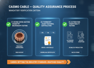
- Cross-section shape: Ask the supplier for a cross-section micrograph. Is it truly round or peanut-shaped? (Peanut = imbalance problem waiting to happen)
- Jacket material: Is it thermoset (GXL/SXL/TXL) or chemically cross-linked PVC? Thermoset is non-negotiable for /15.
- Imbalance testing: Has the cable been measured for AC imbalance per IEEE 802.3 or equivalent? Ask for test data.
- Stripping qualification: Has the cable been tested on actual harness automation (ultrasonic, rotary, or laser stripping)? If not, you're taking a risk.
Network-Level Questions:
- Total backbone length: Including all stubs, what's your actual figure? (Must be <40 m)
- Node placement: Are all nodes within 3 m of the backbone? (Longer stubs = timing failure)
- Grounding strategy: If you're mixing J1939/11 and /15 nodes, who owns the shield handling verification?
- EMC environment: Have you measured or modeled the EMI sources in your vehicle? (Is /15 margin sufficient?)
Why J1939-11 Forgives J1939-15's Mistakes
The honest summary is this: J1939-11 is an error-correcting standard; J1939/15 is an error-sensitive one.
The shield in /11 covers for:
- Sloppy routing (cable near noisy harnesses)
- Asymmetric cable geometry (peanut-shaped cross-sections)
- Edge-rate corner-cutting (suppliers pushing the 200 ns limit)
- Topology flexibility (you can add nodes later without re-engineering)
Take the shield away in /15, and every one of those issues comes back as either:
- An EMC failure (radiated emissions exceed limits during integration testing)
- A harness-shop production problem (cable won't process on automation, rework kills your manufacturing throughput)
The harness shop failure in our opening example wasn't a cable defect—it was a geometry defect. The supplier had been building J1939/15 to /11-era assumptions (that the shield would clean up any asymmetry), then shipping it into an application where that assumption no longer held. Once the supplier built the cable on a non-tight-laid pair with a round thermoset jacket, the strip quality issue went away completely.
The cable is what made the automation path viable. The standard is what made the cable's geometry non-negotiable. Knowing which is which is the engineering discipline.
Frequently Asked Questions
Q1: Can I use J1939/15 cable on a J1939/11 network?
Technically yes, but you're over-specifying. A J1939/15 cable meeting the strict geometry and imbalance limits will work fine on a /11 network. You're paying the /15 geometry premium (which is often higher than the /11 shield cost) for features you don't need. From a cost and engineering perspective, if your network is /11, spec /11.
Q2: What happens if I plug a J1939/11 ECU into a J1939/15 backbone?
The drain wire on the /11 cable must float (not be grounded) on the /15 network side, per SAE J1939/15 Appendix F. If you ground the drain wire, you create a ground loop that violates single-point grounding and can cause intermittent communication failures or radiated noise issues. This is why retrofit scenarios (adding a supplier's /11 ECU to an OEM's /15 backbone) are common sources of field failures—it's a wiring error, not a hardware defect.
Q3: Why does the harness shop say J1939/15 cable won't strip cleanly?
If the cable has a tight-lay (peanut-shaped) cross-section, the jacket is mechanically locked to the conductor twist geometry. When a stripping blade tries to cut a clean ring, it follows the path of least resistance—the helical seam between the two conductors—instead of circling the cable. The result is a ragged strip tail and nicked insulation. This is a cable geometry defect caused by tight-lay construction, not a stripping machine problem.
Q4: Does J1939/15 really only allow 10 nodes maximum?
Yes, per SAE J1939/15 §6.4. The 10-node limit is a timing constraint, not arbitrary. Slower edge rates (required for EMC compliance without a shield) and longer stub lengths consume timing margin. A 30-node network must use J1939/11 shielded cable.
Q5: What is the 10 mV imbalance limit, and how do I measure it?
It's the AC voltage difference between CAN_H and inverted CAN_L, measured with an oscilloscope using AC coupling. In an unshielded pair, asymmetry converts differential signal to common-mode noise, which radiates as EMI. The shield in /11 suppresses this; /15 requires perfect cable geometry instead. Ask your cable supplier for imbalance test data; if they don't have it, you're not buying /15-compliant cable.
Q6: Can J1939/15 work in high-EMC environments like mining equipment?
It's possible but risky. The unshielded topology is more sensitive to radiated noise than /11, and mining vehicles (high-current drilling motors, RF comms, switching power supplies) are severe EMC environments. You'd need to be very disciplined about routing, termination placement, and cable separation. Most mining equipment uses J1939/11 for exactly this reason.
Q7: What jacket material should I specify for J1939/15?
Thermoset cross-linked materials (GXL, SXL, or TXL per SAE J1128) are required. GXL and SXL are the most common; TXL is thinner-walled and lighter. Avoid chemically cross-linked PVC—it's cheaper but harder to extrude with consistent geometry, especially over non-tight-laid pairs. If you need automation-friendly processing, irradiation-cross-linked polyolefin (XLPE) is often the best choice, though it requires more specialized manufacturing.
Q8: How do I know if a J1939/15 cable is automation-compatible?
Ask your supplier three questions: (1) Is the cable built on a non-tight-laid pair? (2) Does the cross-section micrograph show a true round shape? (3) Has it been tested on your specific stripping equipment (ultrasonic, rotary, laser)? If you don't get yes answers to all three, you're gambling with your harness automation timeline.
The Final Thought
You started this research because you needed to pick between two standards. But the real choice isn't J1939/11 versus J1939/15—it's between the disciplined path and the convenience path.
J1939/11 is forgiving. It lets you route the cable however you want, it lets your suppliers build geometry sloppily, it lets you add more nodes later, and it still works. That forgiveness costs money upfront (shielding), but saves money downstream (warranty, rework, integration time).
J1939/15 is efficient. It removes the shield and cuts initial cable cost. But in exchange, every other part of the design becomes non-negotiable: your topology must be locked down, your cable geometry must be precise, your harness automation must be verified, your routing discipline must be absolute. That discipline saves money upfront but requires discipline downstream—and discipline always costs something in engineering time.
The harness shop that couldn't run automation didn't fail because of a bad cable. It failed because the cable supplier was building to J1939/11 assumptions (shield covers everything), then shipping into a J1939/15 application where that assumption no longer held. The engineering problem came first. The cable was just the symptom.
If you're speccing J1939/15, spec it because you've already committed to the discipline. Don't spec it because it's cheaper. By the time you realize the difference, you're already in integration testing.
References
-
SAE International — SAE J1939/11: Physical Layer, 250 kbit/s, Shielded Twisted Pair | Official specification for shielded CAN bus standard in heavy-duty vehicles
-
SAE International — SAE J1939/15: Physical Layer, 250 kbit/s, Unshielded Twisted Pair | Official specification for unshielded CAN bus alternative; includes Appendix F on mixed-layer compatibility
-
SAE International — SAE J1128: Low Tension Primary Cable | Defines GXL, SXL, and TXL insulation/jacket systems; thermoset cross-linking requirements
-
ISO 6722 — Road vehicles — Low voltage electrical systems and components — General specifications | Defines thermal aging requirements (3000 hours at 125°C) and environmental durability for vehicle cable systems
-
IEEE 802.3 — Ethernet Standard | Referenced for differential pair imbalance measurement methodology and AC-coupled oscilloscope testing protocols
-
CASMO Engineering — J1939 CAN Bus Cable Specifications and Manufacturing Guidelines | Practical engineering guidance on J1939 cable selection, topology design, and supplier qualification for heavy-duty platforms
